Welcome to the fourth issue of Volume 3 of PLANE WAVE, Verasonics’ Newsletter through which we share information about new products and technologies, emerging applications, conferences, training opportunities, and collaborations with researchers in ultrasound and ultrasonic technologies. We hope you find these newsletters informative and interesting, and welcome your suggestions for future topics.
New Products and Applications ▪ Technology Information ▪ Research ▪ Conferences and Training
Verasonics’ Solutions for Integrating Custom Transducers
Although the transducer is a fundamental component of every ultrasound device, the development of new transducer technologies is constantly evolving in the field of ultrasonics. Today there are hundreds, if not thousands, of scientists and engineers working on new transducer designs with new shapes, materials and performance characteristics for the development of new ultrasonic applications. Many of these developers are using Vantage™ research ultrasound systems to rapidly prototype their inventions, whether simple or complex. Verasonics offers software and hardware products and accessories to accelerate and assist the latest efforts in transducer development.
Software Tools
Verasonics provides sophisticated, yet easy-to-use methods and tools for developers to evaluate custom transducers. The Verasonics Research Ultrasound Simulator can be used to simulate new transducer designs. For example, a custom transducer with up to 1024 elements operating at a high frequency can be simulated to assess its imaging performance prior to actual construction of the transducer. Different element distributions can be assessed, including sparse aperture arrangements, to determine optimal performance.
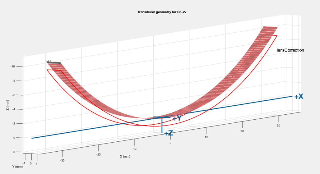
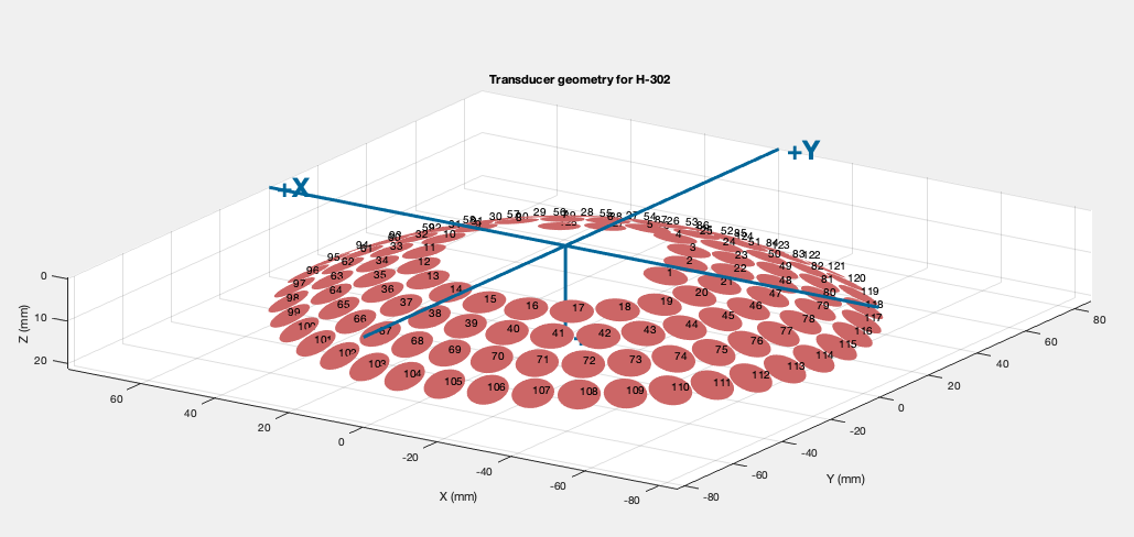
Users are able to rapidly get started with a new transducer by defining and storing key parameters in a MATLAB structure, including the center frequency, number of elements and transducer geometry. Vantage software provides the flexibility for the user to define each element position in three-dimensional space, along with the elevation and azimuth angle for directivity. The software tool called showTrans allows visualization of the transducer geometry for element position verification. As shown in the figures below, the directivity of a convex array and a focused, concave, or “bowl-shaped” array is taken into account for visualization.


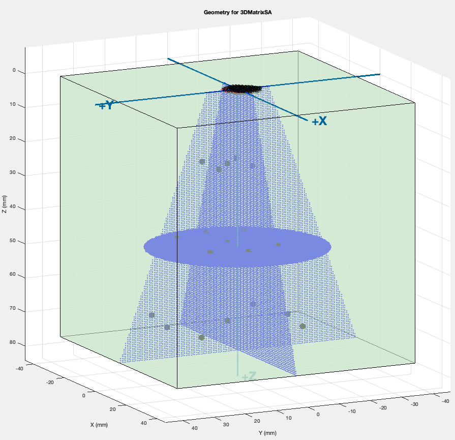
If the transducer is mainly used for pulse-echo experiments, a simple example script with a real-time RF data viewer of each channel is provided. If the objective is image reconstruction, another useful tool is provided to visualize the reconstruction area, i.e., pixel region, relative to the transducer location in 3D space. As shown below, a 2D array is placed at the top of the 3D volume image space displayed in green. The actual pixels for reconstruction are displayed in blue and the grey circles represent the custom-defined media points used in simulation mode.

Hardware Accessories
Almost any transducer can be integrated with the Vantage system using Verasonics’ suite of transducer adapters or transducer accessories. Verasonics offers multiple Universal Transducer Adapters (UTAs) that enable a Vantage user to quickly convert the system to operate transducers with other types of connectors. These UTAs provide the possibility to integrate Verasonics transducers as well as other commercially-available transducers designed for either medical or material applications. Virtually any transducer compatible with one of Verasonics’ UTA pinouts can be integrated. Learn more about Verasonics’ UTA adapters for biomedical research and UTA adapters for non-destructive evaluation (NDE) research.
The Vantage system’s programmability allows for multiple transducer technologies to be integrated. These include, but are not limited to, traditional PZT and single crystal as well as CMUT, PMUT and other cutting-edge technologies. In addition to transducer arrays in the conventional linear, curved and sector formats, Verasonics customers have integrated ring arrays, 2D or matrix arrays, random and sparse arrays, catheter-based arrays, and other novel designs.
Multiple accessories are available to facilitate early transducer development, making it easy to connect prototypes to the Vantage system, including:
The Verasonics Break-Out Board (BOB)
- The Break-Out Board is an ideal prototyping tool for transducer development. A transducer can be physically connected to the BOB in two different ways:
- IDC ribbon (solder free) cables can be used to connect signals to an alternate board or transducer. The benefit of the IDC cable is that a simple cable can be made without the need for complex soldering.
- Wires can be soldered directly to the BOB to connect element signals to a transducer.
- Shielding
- A metal EMI enclosure shields element signals from electromagnetic interference making it a suitable choice for early prototyping.
- Signal Access
- The BOB provides access to the signal paths for 128 elements as well as high voltage multiplexor signals and personality signals.
- Tuning
- The BOB is populated with zero-ohm resistors, but the populated parts can be replaced with a user chosen value to match user-defined requirements. To replace resistors, soldering is required.
The 260-pin ZIF and 408-pin ZIF Back Shell Kits
- These kits provide excellent performance for element connectivity and EMI shielding.
- Both kits offer the electrical components necessary to integrate a custom transducer (not including the transducer cable).
- A metalized back shell is used to create a high-performance EMI enclosure to shield against interference.
- The 260-pin ZIF back shell kit provides for the connection of up to 128 elements, with the 408-pin ZIF back shell kit offering connection of up to 256 elements.
- Series tuning can be used in either configuration.
- Micro-coax termination boards providing signal access are supplied with each kit along with appropriate documentation for connecting element signals.
- Note: the transducer cable must be supplied and defined by the customer.
The 260-pin ZIF Offset Adapter
- The 260-pin ZIF offset adapter provides a low-cost option to gain access to individual element signals. This accessory is useful to users wanting to connect a single element, observe an element signal on external equipment, inject a signal into the Vantage system, or drive a transducer element with external equipment.
- The Offset Adapter allows a user to configure four separate I/O channels with LEMO connectors in the following states:
- Pass an externally sourced signal into one element of the array transducer (and isolate the Vantage channel.)
- Pass an externally sourced signal into one channel of the Vantage system (and isolate the array, e.g., to calibrate the receiver.)
- Connect a Vantage Transmit/Receive channel to an external single element transducer (and isolate from the transducer array, if connected.)
- Observe the signal (voltage and/or current) going between the Vantage and one element of an array transducer (to investigate impedance matching, for example.)
- 4 LEMO-to-BNC cables are provided.
- No shielding is used.
Impedance
In order to deliver optimal power while protecting the Vantage system’s circuitry, it is critical to identify the impedance of the transducer. Verasonics recommends that users input an impedance value or array of impedance values in the transducer definition section of the Vantage software to prevent hardware and/or transducer damage.
Grounding and Shielding
Grounding and shielding have a direct impact on transducer performance. With the 260-pin ZIF and 408-pin ZIF back shell kits, the grounding system for a transducer is expected to perform two functions: (1) to assist in shielding the element signals from ambient electromagnetic interference and (2) to provide a return path for the electrical signals that can be generated by array elements.
Verasonics Community
Verasonics is pleased to offer all Vantage customers access to the Verasonics Community. With over 200 active members, the Verasonics Community continues to grow.
As a web-based portal, the Verasonics Community is designed to provide quick and easy access to helpful tools for training and product information, along with a programming script repository. A new training video on B-mode, Doppler and Image Processing has recently been added, the ninth training video in the series now available to customers.
Already a customer? View the latest training tips, tricks and videos, here.
Visit Us and Learn What’s New at these Upcoming Conferences:
Currently there are no upcoming conferences, however, please join us for our next Vantage customer training via live webinar, 1-4 February, 2021, 9 – 11 am PT.
Please contact [email protected] to register or click here for more information.

