Welcome to the first issue of Volume 4 of PLANE WAVE, Verasonics’ Newsletter through which we share information about new products and technologies, emerging applications, conferences, training opportunities, and collaborations with researchers in ultrasound and ultrasonic technologies. We hope you find these newsletters informative and interesting, and welcome your suggestions for future topics.
New Products and Applications Technology Information Research Conferences and Training
Signal Conditioning in the Vantage Research Ultrasound System Receive Path Adds Flexibility and Efficiency to Research Projects
The Vantage™ Research Ultrasound System includes a high-performance data acquisition platform that provides multiple transceiver channels, receive signal conditioning electronics, deep local memory and a very rapid data transfer rate to its host computer over PCI-express. This Plane Wave issue will describe the Vantage receive path architecture and the programmable signal conditioning available to its users, and how its designed to maximize data quality while minimizing the digital data rate.
The fundamental role of the Vantage receive path is to provide high fidelity per-channel digitized RF data from each individual transducer element with no demodulation, beamforming, or other channel-to-channel processing of any kind. All image reconstruction and post-processing tasks are performed in software on the host computer where the user can control all steps of an imaging application. The hardware signal path for each channel includes an analog section with low noise and high dynamic range amplifiers, followed by an anti-aliasing filter and a digitizer. The digital data stream then passes through an FPGA for signal conditioning before storage in local memory until it is transferred by PCIe to the computer. The digital signal conditioning stage includes two programmable filters and two decimators that can be used to improve the signal to noise ratio and lower the data rate while preserving the desired signal information collected during the acquisition.
Next, we will describe the functional blocks of the analog and digital front-end, and point out the many parameters that can be programmed by Vantage user. As always, Verasonics customers may learn more about these features in the Training Videos available on the Verasonics Community website and in the Vantage Sequence Programming Manual.

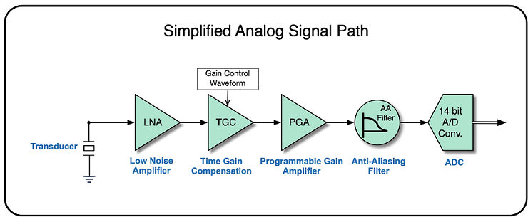
Figure 1: Simplified diagram of the receive path analog front end for each channel
Each receive channel of the Vantage system is essentially composed of the functional blocks diagrammed in above Figure 1 (analog section), and below Figure 2 (digital section). The Low Noise Amplifier (LNA) and Programmable Gain Amplifier (PGA) are fixed and enable user-programmable gain. The LNA input impedance can also be adjusted from a default of about 110 Ω to over 3000 Ω for use with particularly high impedance transducer elements such as those found in matrix arrays, and for other high gain applications such as photoacoustics. The anti-aliasing stage is a 3rd order low pass filter with programmable corner frequency from 10 to 50 MHz. The 14-bit Analog to Digital converter (ADC) has a programmable sample rate from 10 to 62.5 MHz. This converter also has a very fast track and hold circuit and permits digitization of signals at frequencies up to the maximum input frequency of 50 MHz. (For more detail on how you can sample high frequency signals between 25 and 50 MHz with this converter, see our white paper on high frequency data acquisition: Bandwidth Sampling Data Acquisition with the Vantage System for High Frequency Transducers.)

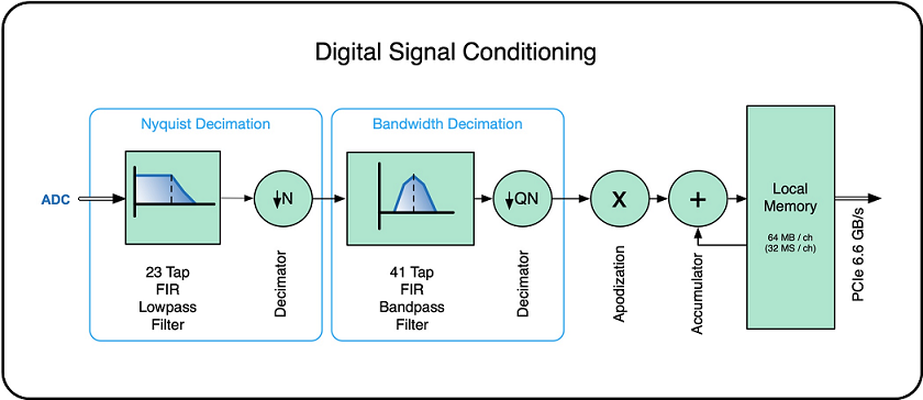
Figure 2: Block diagram representing the digital signal conditioning in the hardware
The digital signal conditioning path is designed to permit digital conversion at a high sampling rate by the ADC while minimizing the data rate to the host controller. This is accomplished by two sets of filters that reduce out-of-band noise and decimators that lower the data rate to the minimum required for faithful representation of the signal captured by the acquisition — the bandwidth and center frequency of that signal depends on the transducer characteristics, the transmit waveform as well as any nonlinear properties of the medium.
The first stage is a 23-tap filter typically intended to low pass the data with a corner frequency set by the signal’s upper band edge; this corner is normally taken to be four times the center frequency and is equivalent to a 200% bandwidth. This is more than the bandwidth of any conventional transducer but provides a convenient data rate for subsequent quadrature demodulation. This 4x sampling rate is often substantially less than the ADC sampling rate, permitting decimation of the filtered data stream. For example, backscattered data from a 5 MHz transducer may have a signal bandwidth of 3 to 7 MHz, been sampled by the ADC at 60 MHz, but only requires a 20 MHz data rate at the 4x frequency to fully represent the data between 0 and 10 MHz, permitting decimation by a factor of 3 with no loss of information.
The second 41-tap stage is typically programmed as a bandpass filter to further reduce noise that is out of the signal band, and also to prepare the data for additional decimation. In the previous example, the signal has less than 100% bandwidth (100 BW/Fcenter), thus permitting another decimation by a factor of two, after suitable bandwidth filtering. The final data rate of 10 MHz thus represents only 5 MHz of signal bandwidth, fully preserving the signal information and also benefiting from the noise reduction obtained by effective averaging of samples originally collected at 60 MHz.
Both filters are symmetrical, that is only 1+N/2 coefficients are needed to specify the response. Additionally, the filters can be combined into one effective 64-tap filter if an acquisition would benefit from a longer filter.
All analog and digital receiver front-end parameter settings are programmed automatically to default values by the Vantage System software, based on the user’s choice of signal bandwidth and the transducer’s nominal center frequency. The default settings are appropriate for “typical” data collection and imaging applications, however users may want to override them to fully optimize performance. Examples of this include applications such as Doppler and/or harmonic imaging where the desired receive signal center frequency and band may differ significantly from the transducer element characteristics specified in the transducer database.
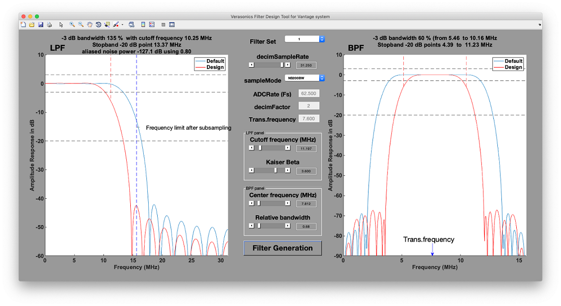
To facilitate custom programming of the digital filter and decimator characteristics, a graphical tool has been developed to visualize the spectral shape of both filters and to adjust control parameters for each filter. A typical view of the Filter Design Tool interface is presented in below Figure 3.

Figure 3: Filter Design Tool interface
Typically, users adjust the cutoff frequency for the Low Pass Filter and the center frequency and bandwidth of the Band Pass Filter, and then confirm that the data rate (parameter decimSampleRate in above Figure 3) is set as desired. When actively running an imaging program, the tool reprograms the filters in real time for immediate visualization of the results; offline operation is also supported. Once the filters have been adjusted to the desired characteristics, the filter coefficients and other settings can be obtained for easy insertion into the application control script.
Two other features are included after the filters. While all channels use the same filter characteristics, each channel can be scaled by a factor between -4.0 and +4.0. This allows for per-channel gain calibration to compensate for differences between transducer elements, for example. Finally, the data for multiple acquisitions can be accumulated prior to transfer to the computer, permitting significant SNR improvements for repeatable experiments. Photoacoustic data collection often includes several hundreds of accumulations to bring out weak signals.
In summary, this article provides a brief description of the programmable features that the Vantage Research Ultrasound System provides to enable high fidelity, per-channel digital RF data acquisition for virtually any research ultrasound application and transducer in the frequency range from 50 kHz to 40 MHz. The Filter Design Tool, one of the many tools included with Vantage software, helps the user to visualize and program the spectral responses of the digital filters in the signal conditioning chain. Users should refer to the Vantage Sequence Programming Manual, as well as other Application Notes and user documentation available from Verasonics for more information on how to use these features and tailor them for optimal performance in specific applications.
The Verasonics Community
In 2018, Verasonics introduced the Verasonics Community, a resource for customers designed to provide quick and easy access to helpful tools for training, product information, along with a programming script repository. It is available at no cost 24 hours a day, 7 days a week. In the past year the Verasonics Community has grown with the addition of new training videos, product documentation and user-contributed programming scripts.
Already a customer? View the latest training tips, tricks and videos, here.
Visit Us and Learn What’s New at these Upcoming Conferences:
Currently there are no upcoming conferences, however, please join us for our next Vantage customer training via live webinar, 1-4 February, 2021, 9 – 11 am PT.
Please contact [email protected] to register or click here for more information.

