Welcome to the third issue of Volume 4 of PLANE WAVE, Verasonics’ Newsletter through which we share information about new products and technologies, emerging applications, conferences, training opportunities, and collaborations with researchers in ultrasound and ultrasonic technologies. We hope you find these newsletters informative and interesting, and welcome your suggestions for future topics.
New Products and Applications Technology Information Research Conferences and Training
Verasonics’ User-Programmable Image Reconstruction Capability Enables Enhanced Accuracy and Speed when Developing Applications
Image reconstruction on the Vantage™ Research Ultrasound System is performed using pixel-oriented processing, a proprietary method of post-processed synthetic beam forming. Synthetic beamforming is ultimately achieved by applying appropriate delay and sum operations to received waveforms such that signals scattered from each given pixel location are coherently compounded. This requires the relative acoustic travel times from transducer elements to each pixel location to be computed.
Verasonics’ image reconstruction computes acoustic path lengths assuming the media has a single homogenous and isotropic velocity, such that there is a straight-line ray path from the pixel location to the transmitting or receiving elements. This is a valid approximation in many imaging applications in both non-destructive testing and biomedical imaging. Indeed, a linear mapping between acoustic travel time and position has been the basis for almost all ultrasonic imaging since its inception.
However, there are applications where geometry or media properties lead to non-trivial, often curved or piece-wise linear, acoustic paths. Unless explicitly accounted for in the image reconstruction algorithm, this can lead to significant reductions in image quality or negate the application entirely, resulting in a non-physical representation of the medium in the image space.
Imaging of non-homogeneous media is a common occurrence in non-destructive testing applications such as immersion measurements, which due to the mismatch in acoustic impedance between liquid and solid media, requires compensation for refraction of the field at a specimen’s surface. There are also material effects such as inhomogeneity through welds, or anisotropy such as is seen in composite and single-crystal metallic components. Further, it is increasingly common to employ indirect imaging modes where, by design, a non-trivial propagation path is considered. Within the field of bio-medical imaging there are also analogous cases where imaging performance may be improved by explicit compensation for such effects. These include aberrations from skull refraction in transcranial imaging or the anisotropy in acoustic velocity introduced by tissue fibrosity, or, by non-uniform thickness of layers of different tissue types such as in the abdominal wall or the breast.
Although development for such applications has always been possible on Vantage systems, they were incompatible with Verasonics standard image reconstruction, requiring the user to implement the beamforming themselves through external processing functions. Historically, the path length calculations used in image reconstruction were performed by the lower level C code and were neither modifiable nor visible to the user. While this remains the default procedure on the Vantage system, since the version 4.2 software release the user now has the option to specify path lengths themselves. By removing the constraint for simple velocity approximations, the image reconstruction is generalized. This enables the user to leverage the accuracy and speed of Verasonics image reconstruction when developing imaging applications in any arbitrary media.
Specifically, the user may specify look-up-tables (LUTs) of transmit and receive path lengths for each pixel in the reconstruction region. For each transmission to be used in a reconstruction, this corresponds to the path from the origin of the beam on the transducer to the pixel location. In the context of generalized full matrix capture/total focused imaging, the user-defined transmit and receive LUT values are simply the path lengths from the pixel location to the transmit and receive elements respectively. Additionally, the amplitude weighting of each transmission can be defined on a per pixel basis, allowing functionality such as dynamic apodization. The user need only specify these LUTs as new fields within pre-existing data structures. Beyond that, there are no differences in sequence programming for User Programmable Image Reconstruction.
Further, since the look up tables can be updated dynamically, Verasonics’ User-Programmable Image Reconstruction provides an ideal framework for the development and implementation of adaptive imaging modes. For specific details on using the Vantage reconstruction capability, refer to the Sequence Programming Manual in the latest software release.
Verasonics’ User-Programmable Image Reconstruction Examples
Here we show two examples of non-destructive imaging applications, which can be developed using the User-Programmable Image Reconstruction. First is the common case of immersion measurements for nondestructive testing. A stand-off layer of water, or some other coupling medium, exists between the transducer and the specimen to be inspected. The path lengths used in beamforming must be corrected to account for refraction of the field at this interface.
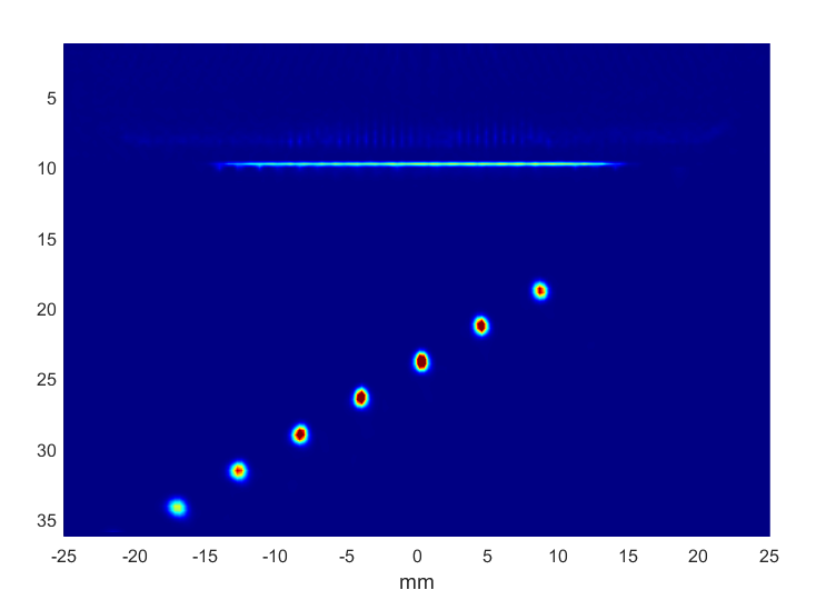
In this example, a 64 element 5 MHz array is used to image a standard ASTM aluminum test block with a water stand-off distance of 10 mm. For each frame, a full matrix acquisition is performed, and the image reconstructed using total focusing of every transmit-receive element pair at each pixel. Within the water layer, the pixels are reconstructed using the simple, direct water paths. Within the material itself, the correct refracted paths from transducer elements to the pixels are used. In this case the specimen face is planar, however the procedure can easily be extended to arbitrary surface profiles. By using path lengths correct for each position in the image, both the front face and holes within the specimen are correctly reconstructed. The 64-channel full matrix capture acquisition and reconstruction of 18,000 pixels was conducted in real-time using a Vantage system at 40 frames per second.

Above: A total focusing method image of an ASTM test block through a water stand-off using Verasonics’ User-Programmable Image Reconstruction.
The second example considers multi-mode imaging. Using the LUT approach to User-Programmable Image Reconstruction, it is straight forward to process the same RF data multiple times using different path lengths. This allows different imaging modalities to be generated from the same acquisition sequence which can then be displayed independently or combined into a single image.

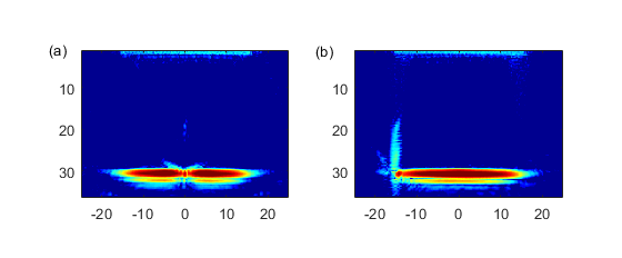
Above: Example of multi-mode direct + half-skip TFM imaging of a fatigue crack (a) array positioned centrally over crack (b) array positioned to side of crack.
The example here combines the trivial direct TFM mode with a non-direct half-skip mode. This second mode shares the direct receive path of the first but evaluates a transmission path which first reflects from the specimen back wall towards the pixel location.
Additionally, this example makes use of the amplitude weighting LUTs. For the half-skip mode, transmitting elements with smaller look angles to the pixel have their contribution to the amplitude weighted lower. The result is for the half-skip mode to be preferentially weighted in regions of the image away from the footprint of the array. Without this weighting, half-skip artifacts from the ballistic pulse would swamp the central portion of the image, obscuring any information from the direct mode.
Imaging is performed using a 64 element 5 MHz array in direct contact with an aluminum fatigue crack specimen. Typical results are shown in the video above. Initially the array is positioned centrally over the crack. In this position, the defect is detected by the direct TFM mode through weak diffraction around the tip. As the array is moved to the side, the half-skip mode becomes dominant and the crack is imaged through the specular reflection from its face. Verasonics’ User Programmable Image Reconstruction allows the seamless combination of the two modes, forming an image which benefits from the different spatial sensitivities of both. The 64-channel full matrix capture acquisition and reconstruction of both modes for 18,000 pixels was conducted in real-time at 30 frames per second.
During the COVID-19 crisis,we are here for you. Verasonics offers ultrasound simulator software that can assist in the continuation of research in a remote setting. Vantage customers have access to five simulator licenses with their system purchase that enable programming and verification of custom acquisition sequences without Vantage system hardware present. This allows for sharing of a single hardware system among multiple users and allows research and development teams to work virtually. To expand your lab’s efficiency while working remotely, Verasonics is offering increased access to the ultrasound simulator software to all customers. Verasonics is pleased to provide an additional five ultrasound simulator software licenses per account on a temporary basis (expires in 6 months). It is our sincere hope that we can support your goals and research during this unsettling time. For more information, please click here.
Upcoming Vantage Customer Training Available Via Webinar:
Please join us for our June Vantage customer training via live webinar. For your convenience, we have two sessions available:
June 1-4, 8am-10am PT or June 21-25, 5pm-7pm PT.
Please contact [email protected] to register or click here for more information.
Visit Us and Learn What’s New at these Upcoming Conferences:
Currently there are no upcoming conferences, however, please join us for our next Vantage customer training via live webinar, 1-4 February, 2021, 9 – 11 am PT.
Please contact [email protected] to register or click here for more information.
Learn how to incorporate Verasonics’ Custom Image Reconstruction into your research projects, contact us.

