Welcome to the second issue of Volume 5 of PLANE WAVE, Verasonics’ Newsletter through which we share information about new products and technologies, emerging applications, conferences, training opportunities, and collaborations with researchers in ultrasound and ultrasonic technologies. We hope you find these newsletters informative and interesting, and welcome your suggestions for future topics.
New Products & Technologies ▪ Emerging Applications ▪ Conferences & Training Opportunities ▪ Collaborations with Researchers
The Vantage System’s Powerful Suite of Programming Features
In our previous Plane Wave (Volume 5, Issue 1), we provided an overview of the Vantage™ Research Ultrasound System utilities and tools designed to assist users in developing and debugging their scripts for sequence programming that come with every Vantage system.
In this Plane Wave issue, we focus on the benefits and potential uses of some of the Vantage features that may assist you in your research efforts.

Figure 1: Folder structure of Vantage feature examples.
Under the Example_Scripts folder (Figure 1), the user can find the “Vantage_Features” subfolder containing example scripts that illustrate many Vantage features. Most of these features are available on all system configurations, with exceptions otherwise noted below.
Vantage Feature:
Extended I/O
The Vantage system is now compatible with an Extended I/O module that provides the capability to seamlessly interface external devices, such as encoders, and digital and analog data acquisition systems, using the Vantage Programming Model for research and development in the NDE/NDT and biomedical fields.
Example Script(s):
Included in the Extended IO subfolder.
These scripts integrate Vantage data acquisition with positioning encoder, analog or digital data captured by external devices.
Vantage Feature:
Low Frequency Configuration
The Vantage platform comes in three bandwidth configurations: Low, Standard and High Frequency. The Low Frequency Configuration has a bandwidth ranging from 50 kHz – 1.5 MHz, suitable for research applications including guided wave tomography and certain types of non-contact ultrasound and ultrasound therapy.
Example Script(s):
Provided in the Low_Frequency subfolder.
The Low Frequency subfolder provides the user a series of scripts on how to program the transmit power controller (TPC) and the analog front-end (AFE) parameters optimally for low frequency data acquisition.
Vantage Feature:
Data Accumulation on Hardware
The Vantage system is capable of accumulating data from multiple acquisitions in hardware and transferring only the accumulated data to the PC. Data Accumulation on Hardware reduces the amount of data to be transferred and lowers the requirement for data storage size, desirable in applications such as photoacoustic imaging, where the received signal is weak and accumulating data from multiple acquisitions can improve the signal-to-noise ratio.
Example Script(s):
SetUpL11_5vFlashAccum
SetUpL11_5vFlashAccum_64LE
These example scripts accumulate acquired data on Vantage hardware and transfer the accumulated data to the controller.
Vantage Feature:
Synchronous/Asynchronous Sequence
The Vantage system can run the hardware and software either synchronously or asynchronously. In a Synchronous Sequence, the Vantage hardware and software are strictly synchronized with each other, such that the data processing will not start until the acquired data is transferred to the PC, and the data acquisition of the next frame will not proceed until the last transferred data gets processed. A Synchronous Sequence guarantees that the data processing does not skip frames.
In contrast, the Asynchronous Sequence allows hardware and software sequencers to run at their own pace. In these cases, the software usually skips frames. The Asynchronous Sequence is typically used in applications where the Vantage hardware acquires data at a frame rate faster than the software processing rate. In this case, it is appropriate for the software to skip frames and only process the most recently transferred data for real-time display.
Example Script(s):
SetUpL11_5vFlashSync
SetUpL11_5vFlashSync_64LE
These are two example scripts illustrating synchronous data acquisition and processing. Examples of asynchronous sequences are provided in many other example scripts named without the “Sync” suffix.
Vantage Feature:
Time Tag/Stamp
RF Data Time Tag/Stamp is a user-programmable feature that, when enabled, overwrites the first two samples of each receive data acquisition event with a 32 bit “time tag” value taken from a free-running counter in the hardware. As a result, the RF data stored in memory from every acquisition event will include a time tag identifying the precise time at which it was acquired relative to other acquisition events with a resolution of 25 microseconds and a range greater than 24 hours.
Example Script(s):
Example scripts are provided in the
RFData_TimeTag subfolder.
These scripts turn on the Time Tag feature, which adds time stamps to acquisitions in the first two samples of RF data. The showTimeTag tool within the folder allows the user to display the timing of the acquisitions.
Vantage Feature:
Transducer Temperature Sensing (UTA 260 or UTA 408 required)
Transducer Temperature Sensing is a Vantage feature that allows monitoring of one or two transducer temperature-sensing thermistors, connected through dedicated pins at the probe connector, for probes that provide this feature. The system can be programmed to automatically monitor the temperature sensors while a script is running and exit the script with an error condition if a predetermined temperature limit is exceeded. The temperatures can also be read from the hardware system whenever desired, for display or other purposes.
Example Script(s):
An Example script is provided in the Probe_Temperature_Sensing subfolder, programmed for temperature monitoring while a sequence is running. An application note is also provided in the subfolder.
Vantage Feature:
Sub-Frame Data Transfer
Sub-Frame Data Transfer is a Vantage feature that provides users the ability to minimize the latency between data acquisition and processing when large blocks of data need to be acquired in a single frame. While the Vantage system can transfer a single frame of RF data as large as 2 GB, this may result in a significant latency from acquisition to processing. This is because the DMA cannot be started until the entire frame has been acquired, and system processing of that frame cannot be started until the entire frame DMA transfer has been completed. To reduce this latency, the Vantage system allows users to subdivide the data from one frame into “subframes” and start transferring the already acquired subframes while the system continues acquiring the remaining data.
Example Script(s):
SetUpL11_5v_128RyLnsSubFrmDma
SetUpL11_5vExtProcSubFrmDma
As part of the Basic features, these two example scripts show users how to program the “subframe” data transfer and how to process the subframe-transferred data.
Vantage Feature:
Push Voltage Monitoring (Extended Transmit option or HIFU required)
The Vantage System can transmit long bursts for acoustic radiation force, waveform coding, or therapeutic ultrasound applications. It may be critically important in some studies to monitor the actual transmit voltage level used. When the Transmit Power Controller (TPC) hardware fault monitoring is turned on, the system will report an error when the actual output voltage deviates more than the user specified thresholds, ensuring the accuracy of the extended burst or HIFU transmit voltage level
Example Script(s):
SetUpL11_5vFlashPushP5Mon
This is an example script for use with the Extended Transmit option or HIFU configuration that enables the Transmit Power Controller (TPC) hardware fault monitoring function.
Vantage Feature:
Driving Multiple Array Transducers (UTA 260-D, UTA 160-DH/32 LEMO, or a custom array connector splitter required)
Simultaneously Driving Multiple Array Transducers can be useful in several applications, including therapeutic ultrasound (Figure 2), pitch catch, and multifrequency acquisitions, etc. The Vantage system allows multiple transducers to be defined in the user setup script and allows users to independently control them through apodization programming.
Example Script(s):
Two example scripts are provided in the Dual_Transducer subfolder. In these scripts, the system is programmed to simultaneously drive two array transducers using a UTA 260-D. In the script “SetUpDualXdcr_HVMux” a non-multiplex and a multiplex transducer are driven simultaneously.

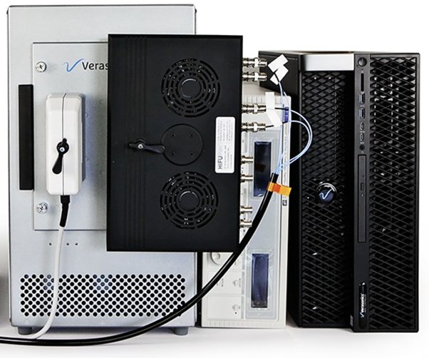
Figure 2. A dual transducer application, where a HIFU array is connected on the right-side connector for therapeutic ultrasound transmission and a phased array is connected on the left-side connector for interleaved imaging.
Vantage Feature:
3D Imaging with Custom Arrays
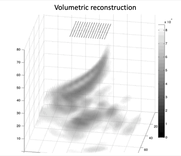
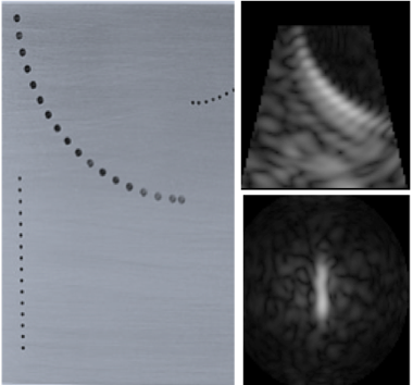
The Vantage system fully supports volumetric imaging and custom arrays. Custom arrays can be described in the user setup script by defining five values per element, specifying the x, y, and z coordinates of the center of the elements and the steering angles of the elements in azimuth and elevation. Besides volumetric imaging display, orthogonal plane imaging can be also reconstructed and rendered in real-time at a higher frame rate to provide preliminary views. Figure 3 shows an example for a custom matrix probe.
Example Script(s):
SetUp_Custom_Transducer_2Darray
This script defines a custom 16-by-16 element matrix array and the sequence for acquisition and display of images along three orthogonal planes (XZ, YZ and XY). This requires the Image Reconstruction license option on the Vantage 32 LE and Vantage 64 systems.


Figure 3. Shown above is a 3D image (left) acquired by the Vantage system with a 1.75 MHz, 16-by-16 element matrix array. The orthogonal plane images in YZ and XY planes (right) are displayed in real-time to guide inspection and data capture.
Vantage Feature:
Conditional Branch
Verasonics sequence programming supports Conditional Branching which can be used to cause the hardware and/or software sequencers to branch to a different sequence event based on a user input from a GUI control. This feature allows users to define multiple sets of sequence events in one user setup script, e.g., for multi-mode imaging, and toggle between them using GUI controls while the sequence is running.
Example Script(s):
SetUpL11_5vIdealCBranch
This script allows the user to alternate between two imaging modes (full synthetic aperture imaging and plane wave imaging) with a GUI control.
Vantage Feature:
Auto Quit
Auto Quit is a programming technique that automatically closes the Vantage Graphic User Interface (GUI) when sequence is complete and returns the control to the MATLAB® command window. The system is then on standby for the next sequence call. This technique allows users to automatically execute several user sequences/scripts sequentially
Example Script(s):
SetUpL11_5vFlash_autoQuit
This script shows an example of how to close the VSX after acquisition is completed using an external process function.
Vantage Feature:
External Processing Function
Leveraging real-time access to the channel data (raw RF data), users can implement “on-line” custom data processing using the External Processing Functions while the Vantage system continues acquiring data.
Example Script(s):
SetUpL11_5vFlashExtFunc
SetUpL11_5vFlashExtFunc_64LE
Example scripts calling MATLAB external functions for custom data processing.
Vantage Feature:
Custom UI Control
The Vantage Graphic User Interface (GUI) comes with built-in UI-Controls allowing dynamic control of sequence parameters that commonly need to be adjusted by users during system runtime (e.g., TGC, transmit voltage, etc.). The GUI also allows users to add custom UI controls, providing the flexibility to change any user-specified sequence object parameters in real-time.
In release 4.3.0 a new more flexible and user-friendly scheme for defining UI Controls and callback functions was introduced. The new approach uses a more advanced object-oriented approach for defining GUI controls, which brings several benefits for the user. For example, now it is harder to make typing mistakes or entering values for parameters that would be invalid. In these cases, an error will be thrown directly when script is executed. Furthermore, now it is possible to define real functions in your script and to pass real function handles to the callbacks of the GUI controls or the external functions. This has the benefit that the user can use tools provided in MATLAB to debug script functions directly.
Example Script(s):
The new preferred and old scheme methods are demonstrated in the two example scripts that are provided in the New UI Scheme subfolder, along with an application note describing all the different UI controls available and their advantages.
Vantage Feature:
Data Import and Export
Data Import and Export is a Vantage feature that provides users an efficient way of exporting and importing data, to and from the PC hard drive, using the Vantage sequence events. Compared with exporting data using MATLAB external process functions, this new feature can provide faster export and data-compression rates. It also provides other benefits including automated file naming/counting, options of data overwriting strategies, and triggered data import/export using the integrated Vantage sequence control commands.
Example Script(s):
Several example scripts are provided in the Data_Import_Export subfolder to illustrate how to import and export data using the Vantage sequence commands. An application note is also provided in the subfolder.
Vantage Feature:
Synchronization of Multiple Systems (Multi-system synchronization module required)
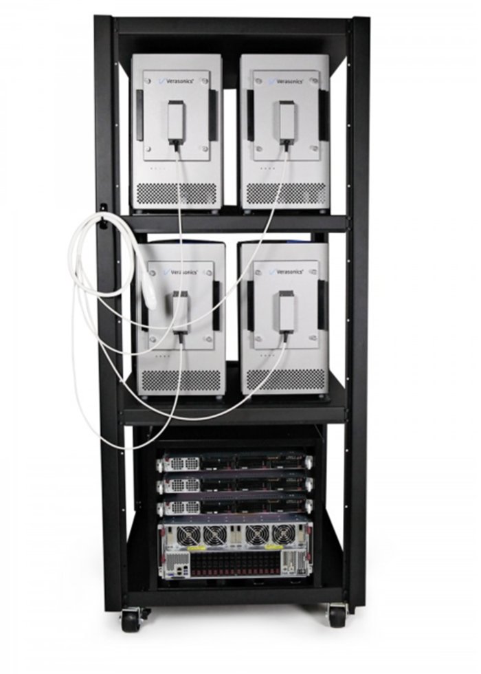
This arrangement permits coherent acquisitions with up to 2048 channels for high-channel-count applications, such as 3D Imaging. Figure 4 shows a solution we provide for 1024-element matrix arrays.
Example Script(s):
Several example scripts are provided in the MultiSystem_Clock_Synchronization subfolder for setting up phase-accurate synchronization of multiple Vantage systems using the multi-system synchronization module.

Figure 4. Verasonics’ Volume Imaging Package with 4 rack-mounted Vantage 256 systems with a 1024-element matrix transducer.
Verasonics is hiring a full-time Ultrasound Scientist!
We are seeking a Research Ultrasound Scientist who is interested in extending their expertise into the commercial facet of research ultrasound. To be successful in this role you will be known for being a self-starter who is able to work independently, and a results-oriented team player who can offer many skills to our growing and deeply experienced science team. You will need to have a deep knowledge of ultrasound physics, experience in programming, and possess an eagerness to learn and help where needed.
Verasonics is an equal opportunity employer. We will not discriminate on the basis of, and all qualified applicants will receive consideration for employment without regard to, race, sex, gender, religion, pregnancy, age, disability, marital status, national origin, genetics/genetic markers, military or Veterans status, sexual orientation, gender identity or any other characteristic protected by applicable federal, state or local law.

