Verasonics offers researchers the most versatile and comprehensive Volume Imaging Solutions available in the market.
Researchers continue to push the limits of ultrasonics, with an increasing need to acquire volumetric data for 3-dimensional imaging and analysis. Rapid acquisition is essential in many biomedical applications – requiring high frame-rates of RF data, using specialized transducers supported by high-channel count electronics.
Verasonics is an experienced leader in the acquisition of volume imaging data, offering a variety of solutions for use across a wide range of studies, including 2- and 4-unit multi-system configurations.
Vantage NXT volume imaging packages & software
Volume Imaging solutions from Verasonics have been developed to enhance and extend the work of today’s scientific community. Volume Imaging Essential and Expansion Packages, combined with appropriate transducers and UTAs, can streamline research efforts. Package offerings:
- Essential Package includes two Volume Imaging RDMA licenses, data cables and a Vantage NXT Multi-System Synchronization Module
- Expansion Package includes two additional Volume Imaging RDMA licenses, 4 rack-mounted host controllers, data cables, multi-system rack assembly and remote installation support
Note: Expansion Package requires the purchase of the Essential Package
Verasonics provides the software required for acquisition and reconstruction of volumetric data. The software includes scripts for a variety of 3D acquisition techniques such as plane wave, wide beam, and random compound aperture imaging, as well as color Doppler imaging using matrix array transducers. Verasonics also offers scripts for volumetric acquisition using row-column array transducers.
Potential benefits of high-frame rate volume imaging:

Verasonics offers researchers the most versatile and comprehensive Volume Imaging Solutions available in the market.
Researchers continue to push the limits of ultrasonics, with an increasing need to acquire volumetric data for 3-dimensional imaging and analysis. Rapid acquisition is essential in many biomedical applications – requiring high frame-rates of RF data, using specialized transducers supported by high-channel count electronics.
Verasonics is an experienced leader in the acquisition of volume imaging data, offering a variety of solutions for use across a wide range of studies, including 1-, 2- and 4-unit multi-system configurations.
Vantage NXT Volume Imaging Packages & Software
Volume Imaging solutions from Verasonics have been developed to enhance and extend the work of today’s scientific community. Volume Imaging Essential and Expansion Packages, combined with appropriate transducers and UTAs, can streamline research efforts.
- Essential Package includes RDMA licenses, cables and support for 2 systems, plus a Vantage NXT Multi-System Synchronization Module
- Expansion Package includes two additional RDMA licenses, 4 rack-mounted host controllers, plus necessary hardware and accessories for a 4-system configuration
Verasonics provides the software required for acquisition and reconstruction of volumetric data. The software includes scripts for a variety of 3D acquisition techniques such as plane wave, wide beam, and random compound aperture imaging, as well as color Doppler imaging using matrix array transducers. Verasonics also offers scripts for volumetric acquisition using row-column array transducers.
Potential benefits of high-frame rate volume imaging:
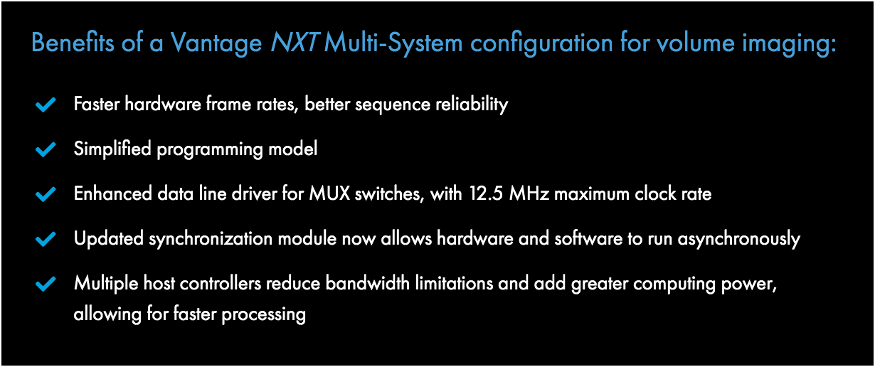
Benefits of a Vantage NXT Multi-System configuration for volume imaging:
Volume Imaging Options
| System Configuration | 1 System | 2 System | 4 System |
|---|---|---|---|
| Vantage NXT 256 System (MF/HF) | 1 | 2 | 4 |
| Number of Receive Channels | 256 | 512 | 1024 |
| Maximum Number of Connected Elements | 1024 | up to 2048 | up to 4096 |
| Host Controllers | 1 | 2 | 4 (one primary / three secondary) |
| Volume Imaging Package - Essential | ✓ | ✓ |
|
| Volume Imaging Package - Expansion | ✓ |
Single system, 256-channel solution:
A single Vantage NXT 256-channel system can be connected to different subsets of matrix array elements on transmit and receive to obtain synthetic aperture ultrasound data. The data can be processed by the Vantage NXT system software to yield volume image reconstructions. To obtain larger aperture data from matrix array transducers, multiple Vantage NXT systems can be synchronized to provide up to 1024 channels of acquisition data.

Vantage NXT with UTA 1024-MUX and Matrix Array Transducer
Multi-system solutions:
A researcher can start with one Vantage NXT system and later acquire additional systems that can be synchronized to provide a larger number of acquisition channels. A 2-system configuration would provide researchers 512 receive channels, providing data from up to 2048 elements.
The 4-system configuration of the Vantage NXT has 1024 transmit and receive channels, with the potential for up to 4096 element signals with 4 x 1024-muxes. The most comprehensive volume imaging offering from Verasonics, it enables the fastest possible data acquisition from high-element-count matrix arrays.

Vantage NXT 4-unit Multi-System
Vantage NXT Multi-System Synchronization Module

One challenge in combining multiple systems for research or product development is the synchronization of transmit and receive clocks for each system for phase-accurate image reconstruction. The Multi-System Synchronization Module allows users to synchronize the 500 MHz system clocks in individual Vantage NXT systems to within 1ns and is included in the Volume Imaging Packages.
Vantage NXT Multi-System configurations define one system as the primary, with one or more secondary systems. Identical conditionally programmed scripts run on each system and sequences are synchronized through the module. High speed networking adapters transfer RF or partially beamformed IQ Data from the secondary systems to the primary host controller using RDMA technology. A typical sequence would perform partial image reconstruction on each of the host controllers with a final summation and display on the primary host controller.
11335 NE 122nd Way, Suite 100
Kirkland WA 98034

